Contents
- Introduction
- Sample preparation facilities
- Sample stages & environments
- Transport & Safety
- Waste disposal
- Sample set-ups with examples
- Transmission experiments
- Reflection experiments
- Grazing Angle Objective (GAO) experiments
- Attenuated Total Reflection (ATR) experiments
- Linkam FTIR600 sample stage
Introduction
The IR microscopes can record spectra from a range of different samples; from thin microtomed sections to polished blocks and embedded particles. The nature of the sample generally determines the required sampling configuration (transmission, ATR etc.). Some examples with preparation details are given below. Click on headings for more information.Sample preparation facilities
Limited space is available inside the IR Cabin for sample preparation, however the synchrotron has both a Chemistry and a Biochemistry laboratory on-site. These are equipped with fume cupboards, fridges, freezers, pellet press, ovens, stereo microscopes with camera, UV-Vis spectrometer and balances. A microtome is also available onsite (see our FAQ page). Please consult IR Beamline staff if you require specific equipment for sample preparation so we can ensure you have access to it over your beamtime. If it is something we do not have, you may have to supply your own equipment.In addition to the above, PC2 cell culture facilities are also available for use. The Biochemistry lab is PC2 compliant and set-up for bacterial and GMO work, and a PC2 Tissue Culture laboratory is available for mammalian cell work. Facilities include a Class II Laminar Flow Biosafety Cabinet, CO2 incubator, inverted microscope, autoclave, centrifuges, fridge, freezer and water bath. Users requiring access to these facilities should contact IR beamline staff when submitting their proposal if it involves the handling of live biological material.Please note that in special circumstances site access can be given earlier than your scheduled experiment if you require time to prepare your samples onsite e.g. you require the microtome or the PC2 laboratory.Sample stages & environments
Each microscope is equipped with a motorised sample stage and can accommodate samples up to approximately XxY = 10x10 cm in size. Maximum sample thickness is restricted to 10 mm by the vertical travel limits of the stage and the working distance of the objective optic. The stage is fitted with interchangeable plates which can be adapted for different sample shapes and sizes.Typical sample sizes accommodated within these plates include:- 13 mm or 22 mm diameter optical windows (transmission; click here for commonly used materials)
- 25x76 mm (1”x3”) microscope slides (reflectance)
- 50x76 mm sample chambers (e.g the micro-compression cells, Linkam FTIR600 sample stage)
To reduce the background variations produced by the presence of water or carbon dioxide in the atmosphere, each microscope stage is surrounded by a perspex box continuously purged by dry air. In addition, use of the Linkam FTIR600 sample stage also allows the immediate environment surrounding a sample to be controlled; samples are placed within a small chamber in the heating block that can be purged by either nitrogen or argon gas. This stage can be used for samples in either transmission or reflection mode; click here for more details.
For specific requirements relating to sample mounting, please consult the IR beamline staff.
Transport and safety
Please see Sample Transport & Safety for more specific information.Please consult your OHSE if unsure how to best transport your samples. If you have air- or moisture-sensitive materials, it is recommended you transport samples in a sealed box supplied with desiccant. An electric desiccator (10% humidity) is available in the IR Cabin to store samples if necessary.Waste disposal
Please see Waste Disposal for more specific information.You must remove all waste from the beamline for disposal at your own facility. Some waste disposal facilities are available in the Chemistry and Biochemistry Laboratories. Please consult IR Beamline staff for more information.Sample set-ups with examples
Transmission experiments
Solid samples should be microtomed to a thickness of between 5-10 microns, either freestanding or mounted on IR transmitting windows such as CaF2, BaF2, ZnSe, preferably 0.5 mm in thickness, or less frequently Si or Si3N4 less than 500 nm in thickness; your choice depends on the window properties and your required wavenumber coverage (consider the IR transmission range of the window material; click here for more information). We also recommend Crystran Ltd, www.crystran.co.uk, for further details. A micro-compression cell with diamond or CaF2 windows, to sandwich your sample in place under the beam, is also available for use.
Examples of samples for transmission:- Biological tissues – microtomed and mounted onto an IR transmitting window
- Cultured cells – grown on a substrate such as CaF2 or silicon nitride windows, and freeze-dried or fixed and air dried
- Polymer multilayers – microtomed and placed in a compression cell between two windows of diamond or CaF2
Reflectance experiments
It is vital that the surface of your sample be ‘optically polished’ to a roughness of 1 micron or less, to reduce scattering of the reflected beam and other interference features. If possible, we recommend that you deposit your sample as a relatively thick layer (1-20 microns) on a non-IR absorbing, reflecting surface e.g. a highly polished metal slide (Au or Al), and also that a blank area be left on the substrate for reference measurements. Experiments on layers thinner than this typically require use of grazing angle reflection (see below).
Examples of samples for reflection:- Minerals - finely polished with alumina or diamond to a surface roughness of 1 micron or less
- Biological tissues or cultured cells mounted or grown on reflective surfaces, such as Mirr-IR microscope slides (Kevley technologies, Ohio) or gold coated glass
Grazing incidence angle experiments
Specifically designed for the study of thin layers or films <1 micron thick and deposited onto non-IR absorbing, reflecting surfaces e.g. highly polished metal slides (Au or Al). Samples must be optically flat to the IR beam, and ideally an uncoated/untreated area should be left on the sample surface to record the reference spectrum.
Examples of samples grazing angle experiments:- Thin (sub micron) coatings on metallic or other highly IR-reflective surfaces
- Corrosion products on metallic surfaces
ATR experiments
For IR non-reflective, ‘hard’ materials that cannot be microtomed for transmission experiments. The ATR Ge crystal tip is pressed directly onto the surface for IR analysis. For best results, where possible the surface should be ‘optically polished’ to a roughness of around 1 micron or better, or alternatively the surface may be microtomed to expose a smooth surface for analysis.Samples are best mounted on 25 mm diameter metal disks, or embedded in resin disks of the same dimensions. The sample positioning stage of the macro-ATR has limited travel, so however your samples are mounted, the region of interest must be located within the central 5 x 5 mm of the 25 mm diameter disk.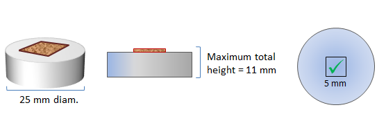
Figure 1. Mounting samples for macro-ATR analysis. We have a range of disks available at the beamline (fig.2) from 2 mm high to 10 mm high and disks with the option of sample heating/cooling.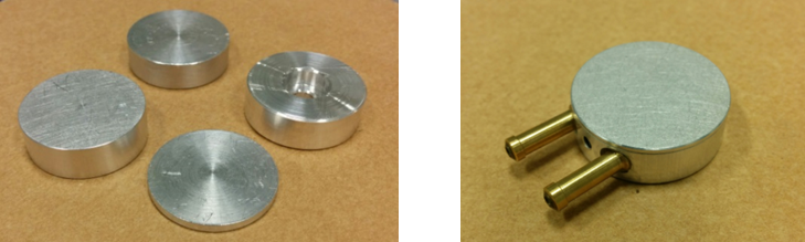
Figure 2. Metal disks for mounting macro-ATR samples. Left: metal disks of different heights. Right: metal disk for sample heating/cooling.
- Fibrous materials - paper or parchment, inks or pigments on rough surfaces such as paper
- Hard materials - paints, minerals or bone; surfaces should be optically polished to a roughness of 1 micron or better
- Paint multilayers - paint chips embedded in resin and polished with alumina or diamond paste to expose a flat surface. Alternatively, for softer samples a microtome can be used to create a flat surface for analysis
The Linkam FTIR600 sample stage
- Transmission - the central aperture through the sample stage is 3 mm in diameter. Samples can be either slightly larger than this and self-supporting or deposited onto IR transmitting windows e.g. CaF2, BaF2, ZnSe, 16 mm in diameter (up to 22 mm without XY manipulation) and 0.5-1 mm thick; click here for further details.
- Reflection - samples can be up to 16 mm in diameter (up to 22 mm without XY manipulation) and up to 1 mm thick.
- NOTE Ideally in both cases a blank area should be left on your sample for reference measurements.