Contents
Introduction
A number of different accessories can be coupled to our FTIR microscopes to assist with experiments. These include:
For the analysis of living biological cells, we offer:
- when available, liquid compression cells for the study of live microbiological systems (figs. 7 & 8)
- a liquid flow-through cell (fig. 9) where the conditions surrounding living systems can be altered to monitor effects in close to real-time
Some basic information regarding each mode of operation can be found below. Click
here for information on sample preparation for the different methods.
Transmission
Transmission IRM is recommended where possible and can be used for solid, liquid or gaseous samples. Transmission requires that samples be very thin (between 5-10 microns where possible) and flat, highly polished where applicable and either freestanding or deposited onto an IR transmitting window such as calcium fluoride (click
here for more details on the types of IR transmitting materials commonly used). See
Samples for more information.
 |
| Figure 1. The Bruker 36x focusing objective and condenser. |
Combined IR transmission studies & X-ray Microscopy
Samples can be analysed by both transmission IRM and X-ray fluorescence microscopy at the
X-ray Fluorescence Microprobe (XFM) beamline when they are deposited on silicon nitride (Si
3N
4) windows. NOTE Window thickness is restricted to a maximum of 500 nm and the material shows a lower wavenumber cut-off in the mid-IR at 1100 cm
-1. Please contact a
Beamline Scientist for more information.
Reflection
Reflection studies measure the specular reflectance or transflectance from the surface of a sample. For samples that can reflect IR directly (specular reflectance), it is vital that they be ‘optically polished’ to reduce scattering of the reflected beam and other interference features; see
Samples for more information.
Transflectance studies are more commonly conducted at the beamline and describe the reflection observed when a sample is deposited as a relatively thick layer (1-20 microns) on a non-IR absorbing, reflecting surface e.g. a highly polished metal slide (Au or Al). Experiments on layers thinner than this typically require use of our Grazing Angle objective (GAO) (see below). Transflectance effectively produces a double-pass transmission spectrum as the beam passes through the sample twice upon reflection, however scattering effects from the surface can impact the data and transmission measurements are preferred where possible.
Back to top
Grazing Angle Objective (GAO)
The IRM beamline has a Bruker Vis/IR Grazing Angle Objective (GAO), fig. 2, for grazing incidence analyses. This objective is specifically designed for the study of thin layers or films <1 micron thick and deposited onto non-IR absorbing, reflecting surfaces e.g. highly polished metal slides (Au or Al). GAOs increase the optical path length of a sample by essentially skimming the beam across the surface using high angles of incidence. This objective uses an incident angle of ~84° and shows excellent sensitivity down to monolayer thicknesses, particularly when used with polarised light, and good spatial resolution; tests indicate 10 microns best spatial resolution when using a 10x10 micron aperture and the synchrotron source (fig. 3). The Bruker design relies on tranflectance from the sample surface, effectively increasing the sample path length to again assist sensitivity, and uses a polariser in the IR beam; p-polarised light is polarised perpendicular to the surface of the sample and shows enhanced IR absorption when large angles of incidence are used. s-polarised light is polarised parallel to a surface and shows minimal absorption.
") |
| Figure 2. The Bruker Grazing Angle Objective (GAO) (15x zoom). |
 |
Visible image of USAF Resolution Test Target: Group 4 Element 4. 22.62 cycles/mm (the width of each line is 22.10 microns). An FTIR grid map overlays the image. |
 |
FTIR 2D chemical map showing resolution of test target lines over integrated region 2900-3500 cm-1. |
 |
FTIR 2D chemical map showing resolution of test target lines over 1300-1350 cm-1. |
|
Figure 3. Comparitive Vis/IR image showing resolution of GAO. FTIR conditions: 45x17 grid, 10x10 micron aperture, 10 micron step size, 128 averages per point.
NOTE: Visual images taken using this objective are stretched in the horizontal direction as light striking the sample is at the grazing angle of incidence. This distorts the focused spot size (aspect ratio 4:1) and influences spatial resolution in the IR mode; vertical lines are more difficult to resolve than horizontal lines. The centre of the IR image is also shifted by approximately 80 microns to the left and 20 microns down from the centre position of the visible image.
|
Back to top
Attenuated Total Reflection (ATR)
ATR relies on a form of internal reflection to enable the analysis of more ‘difficult’ samples with IR spectroscopy, e.g. samples that cannot be microtomed for transmission measurements or that do not adequately reflect IR for reflection; see
Samples for more information regarding sample types and preparation for ATR.
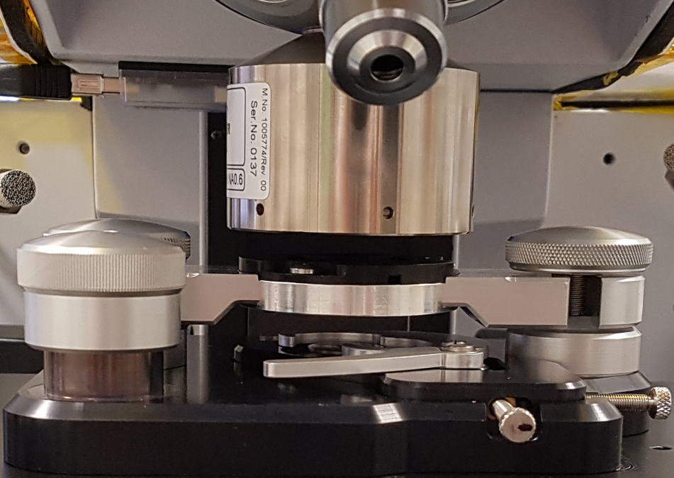
The IR beamline has a Bruker single-bounce macro-ATR accessory, fig. 4(a), with a Germanium crystal tip (refractive index=4) mounted on a macro-ATR cantilever arm, fig. 4(b). There are three different Ge diameter facet sizes available for use: 1 mm, 250 microns and 100 microns. When the Ge tip is pressed into contact with a sample, radiation at the Ge/sample interface interacts with the surface of the sample via an ‘evanescent wave’; the depth of penetration in the mid-IR region is <2microns, dependent on both the wavelength of the radiation (greater penetration at lower wavenumbers) and distance from the Ge surface.
 |
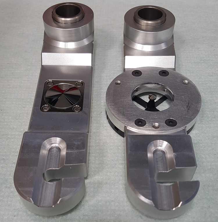 |
Figure 4(a). The Bruker macro-ATR unit and set up with 20x objective.
|
Figure 4(b). Macro-ATR cantilever arms. Left: original model with 1 mm dimater facet Ge crystal. Right: hybrid version in-house modified to to accept a 250 micron or 100 micron facet Ge crystal. |
Micro-compression cell; available for use with diamond windows
A Thermo micro-compression cell, fig. 5, is available to assist with sample preparation for transmission studies. The cell uses two 13 mm diameter, IR-transparent windows e.g. calcium fluoride, barium fluoride, etc., to sandwich a sample under moderate compression. This both supports the sample and flattens and thins the sample for analysis. The Thermo cell can also be fitted with two diamond windows, enabling extremely high pressures to be applied to a sample.
 |
| Figure 5. The Thermo Diamond micro-compression cell. The diamond windows are shown; the diamond is centered in the metal discs creating a sample window 2x2 mm2 in size. |
The Linkam Sample Stage (FTIR600)
This sample stage can be heated up to 600°C and cooled to -196°C/liquid nitrogen temperatures, at heating rates of up to 150°C/min and linear cooling rates of 0.01 to 100°C/min, fig. 6. The sample is placed within a central gas tight chamber for atmospheric control; we can supply argon or nitrogen gas for this purpose. The stage can be used for samples in either transmission or reflection mode; see
Samples for more information. More details regarding the stage itself can be found on the
Linkam website.
 |
| Figure 6. The Linkam FTIR600 sample stage. |
Liquid compression cells for the study of live microbiological systems
A major restriction to studying living systems by IR is the strong absorbance of water in the mid-IR region which overlays the amide I band (1650 cm-1) of proteins and complex biological materials. This limits measurements to samples with a path length of <10 microns, and a liquid cell designed at the Australian Synchrotron* enables the collection of high quality, mid-IR spectra of live mammalian cells at these small path lengths. The design utilises a micro-compression cell, fig. 7(a), to sandwich biological cells between two calcium fluoride windows (13 mm in diameter), fig. 7(b), one of which is printed with a micro-fabricated spacer 6 microns in thickness. The s-channels in the spacer allow excess water to squeeze out from between the plates when a cell suspension is compressed. The design has an approx. 40-60 minute hold time before the water evaporates completely. NOTE This set up is not always available for use.
Another sample holder also designed and available at the beamline is shown in fig. 8(a). This cell again sandwiches biological samples between two calcium fluoride plates (40 mm in diameter) but uses spacers made out of Mylar (6 micron thickness) or Kapton (7 micron thickness), fig. 8(b), which you lay onto the bottom window before adding your sample. This setup can be used in both static and flow-through modes.
Please contact a
Beamline Scientist if you wish to use either of these sample holders and for more detailed information on these designs.
NOTE PC2 cell culture facilities are available for use onsite to help set up these types of experiments. Click
here for more information.
 The liquid compression cell") |
, Calcium fluoride window with a 6 um micro-fabricated spacer") |
Figure 7(a). The liquid compression cell for static biological samples. Uses a modified Thermo micro-compression sample holder.
|
Figure 7(b). 13 mm diameter Calcium fluoride window printed with a 6 micron micro-fabricated spacer. |
 The liquid compression cell for static or flow-through experiments") |
. Showing the Mylar spacer (5 micron thickness) being placed into position") |
| Figure 8(a). The liquid compression cell for static biological samples or flow-through experiments. The two calcium fluoride windows, 14 mm diameter, are visible. |
Figure 8(b). Showing the Mylar spacer (6 micron thickness) being placed into position. |
* M. J. Tobin, L. Puskar, R. L. Barber, E. C. Harvey, P. Heraud, B. R. Wood, K. R. Bambery, C. T Dillon and K. L. Munro, Vibrational Spectroscopy, 53; 34-38 (2010)
Back to top
A liquid flow-through cell for the study of live microbiological systems
A Bioptechs flow cell designed for light microscopy has been adapted for FTIR microscopy; see fig. 9. The design uses a peristaltic pump to flow a film of media around live biological cells. Their response to changes in this media can then be measured in almost real time. Please contact a
Beamline Scientist if you wish to use this sample holder. For more details on the cell itself, please see the
Bioptechs website.
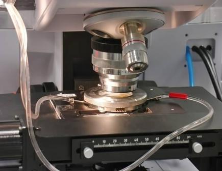 |
| Figure 9. The modified Bioptechs liquid flow-through cell. The cell is shown in place on the Hyperion 2000 microscope stage. |